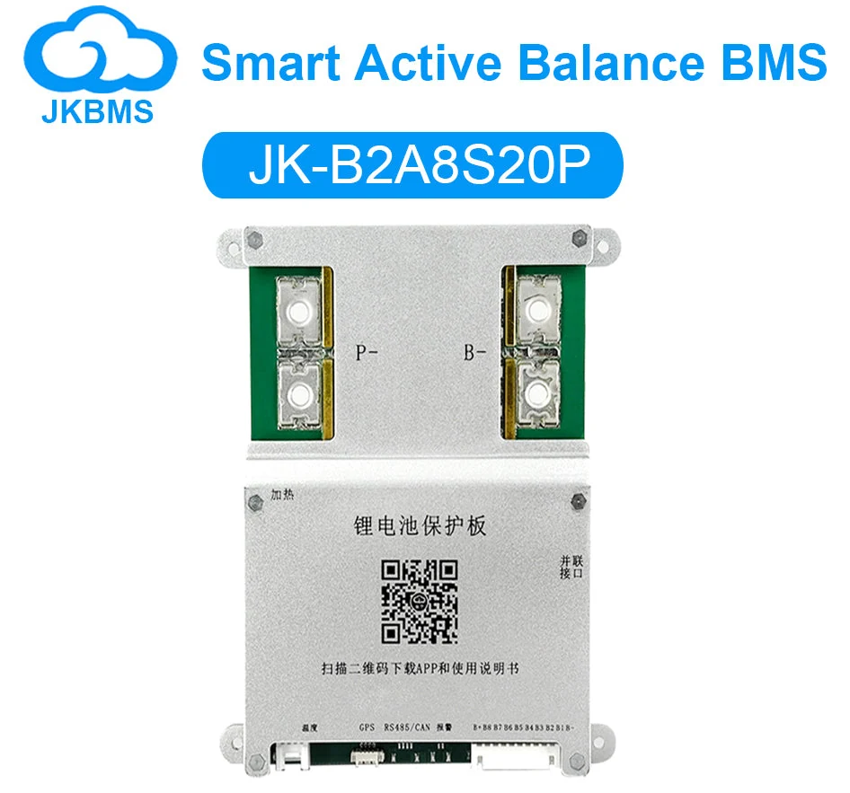
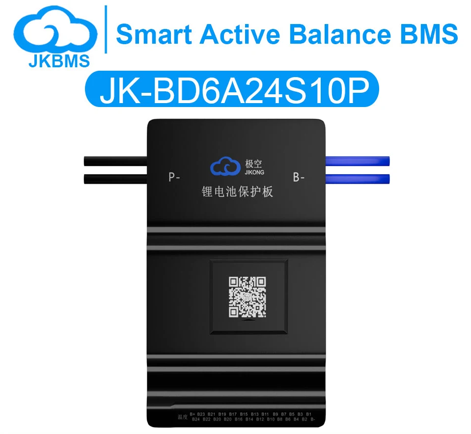
Common port vs separate port: what actually changes
Technical review pending — checked against public standards on
- topology
- selection
One connector or two. The difference decides whether your charger and your load can have independent limits — and how much heat the board makes.
Port topology is about which terminals the charge current and the discharge current share. It sounds like a wiring detail. It is actually a decision about what the board can control independently.
Common port
Charge and discharge both pass through the same pair of terminals. One switch group sits between the cells and that pair.
- Fewer terminals, less wiring, smaller footprint
- Charge and discharge share the same current path, so the board must be sized for whichever is larger
- Cannot independently limit charge and discharge current — the switch is either on or off for both
- Typically lower cost at the same current rating
Common port suits systems where charge and discharge currents are similar in magnitude — a solar storage pack, a small traction pack, most RV installations.
Separate port
Charge and discharge have their own terminal pairs and their own switch groups. The board can open one path while leaving the other closed.
- Independent limits: a large charge source and a small load can coexist without oversizing the load path
- Can keep the load powered while blocking charge — useful when a charger misbehaves or a cell is over-voltage
- More terminals, more wiring, larger board
- Higher on-resistance in total, because current passes through two switch groups over the system lifetime
What does not change
Protection logic is the same in both. Over-voltage, under-voltage, over-current and over-temperature all still apply per cell and per pack. Port topology changes which path the board can interrupt, not what it monitors.
Balancing is also unaffected. Balancing happens between cells, on the cell side of the switch groups, so it runs whenever the board is powered regardless of which port is open.
A wiring consequence people miss
On a separate port board, the charger negative and the load negative are not the same node. If you bond them anywhere else in the system — a shared chassis ground, for instance — you have created a path around the charge switch, and the board can no longer stop charging. The symptom is a pack that keeps charging after the BMS reports a charge disconnect.
How to decide
| Situation | Common port | Separate port |
|---|---|---|
| Charge and discharge currents similar | Preferred | Works, no benefit |
| Large charge source, small load | Oversized load path | Preferred |
| Small charge source, large load | Oversized charge path | Preferred |
| Tight space, minimal wiring | Preferred | Harder to fit |
| Shared chassis ground in system | Preferred | Needs isolated charger |